
Precision Powertrain Components | Uncompromised Performance Legacy
Core-Driven Innovation | Redefining Aftermarket Excellence
Views: 0 Author: Site Editor Publish Time: 2026-09-27 Origin: Site


Strict global emissions standards necessitate precise control over Nitrogen Oxide (NOx) reduction. Modern regulations demand high performance without compromising engine power output. To meet these ambitious environmental targets, vehicle manufacturers rely heavily on advanced exhaust gas recirculation systems. As engine management systems have evolved, the mechanisms controlling exhaust gas recirculation have shifted significantly. This technological transition complicates diagnostics, replacement strategies, and fleet maintenance routines. Technicians now face new diagnostic hurdles when isolating mechanical versus electrical faults across different actuation types. This article compares the operational realities, failure modes, and implementation requirements of electronic and pneumatic systems. You will learn how to differentiate their core architectures and identify their primary vulnerabilities. Ultimately, this knowledge guides accurate troubleshooting workflows and informs smart procurement decisions.
Pneumatic systems rely on manifold vacuum and mechanical diaphragms, offering durability but lacking the micro-adjustments required by modern emission standards.
Electronic systems use ECU-driven stepper motors or solenoids for rapid, highly precise flow control, though they are more vulnerable to heat and electrical faults.
Failure modes differ fundamentally: Vacuum leaks primarily plague pneumatic types, while carbon-induced motor binding and sensor failure dominate electronic types.
Procuring a reliable aftermarket EGR valve requires strict adherence to OEM actuation specifications; electronic and pneumatic valves are not interchangeable.
The automotive industry experienced a massive engineering shift moving from mechanical systems to digital engine management. You can trace this evolution directly to the tightening of global emissions standards. Early environmental regulations required basic NOx reduction, which mechanical systems handled adequately. However, as standards like Euro 6 and stringent EPA mandates emerged, engineers needed far greater precision. They had to control combustion temperatures dynamically under varying engine loads. This strict compliance landscape drove the transition from simple mechanical vacuum designs to complex ECU-mapped recirculation modules. A modern EGR Valve must react instantly to telemetry data to keep NOx levels within legal limits.
Engine efficiency and fuel economy also played a massive role in this shift. Precise gas metering prevents engine hesitation, rough idling, and unnecessary fuel waste. When an engine receives too much exhaust gas at idle, it chokes and stalls. Conversely, if it receives too little during acceleration, combustion temperatures spike, causing harmful pre-ignition or engine knock. Upgrading the actuation method allowed engineers to program highly specific gas flow maps. We now see systems that deliver the exact volume of inert gas required for optimum thermal efficiency. This prevents wasted fuel and protects internal engine components from extreme heat.
This technological leap introduced significant diagnostic complexity. Fleet managers and mechanics must account for the business cost of vehicle downtime. Older mechanical systems require physical vacuum testing using hand tools and visual inspections. Technicians often spend hours tracing cracked hoses or testing mechanical diaphragms. In contrast, modern electronic systems integrate directly with onboard diagnostics (OBD-II). They provide faster troubleshooting paths by generating specific fault codes. Yet, this digital integration brings its own challenges. Mechanics must now differentiate between mechanical binding, wiring harness degradation, and internal sensor failure. You need advanced bidirectional scan tools to actuate components digitally, shifting the diagnostic skillset from physical mechanics to electrical engineering.
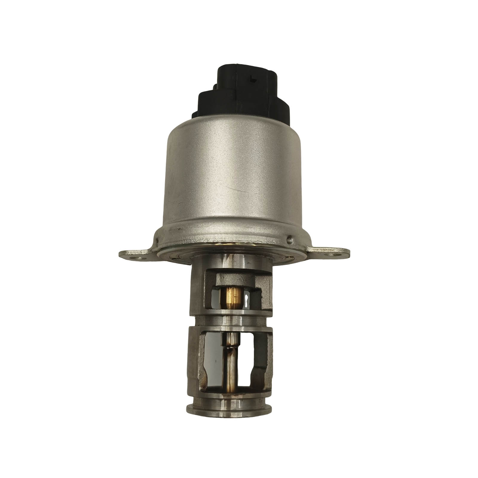
The traditional vacuum EGR valve operates on a purely mechanical principle. It is actuated by engine vacuum pulling against a spring-loaded diaphragm. When the engine reaches a specific operating temperature and load, vacuum pressure routes to the top chamber of the assembly. This vacuum overcomes the spring tension, lifting the pintle off its seat and allowing exhaust gases to flow into the intake manifold. Engineers often regulate this process using a secondary Vacuum Switching Valve (VSV). The VSV acts as a gatekeeper, opening or closing the vacuum line based on basic thermal switches or early electronic signals.
This architecture remains completely reliant on physical integrity. It depends heavily on the condition of the rubber vacuum hoses and the available intake manifold pressure. Furthermore, the internal diaphragm elasticity dictates how smoothly the pintle moves. If the diaphragm tears or hardens due to age, the entire assembly fails to open. These systems dominate pre-2000s passenger vehicles. We also see them frequently in legacy heavy-duty diesel engines and simpler industrial agricultural applications. They offer rugged simplicity but lack the intelligence required for precise flow mapping.
Modern engine bays almost exclusively feature the electric EGR valve. Unlike its mechanical predecessor, this component is actuated by a rapid digital signal from the Engine Control Unit (ECU). The ECU drives an internal solenoid or a highly geared stepper motor. This motor physically pushes or pulls the pintle shaft to exact micro-positions. To ensure accuracy, manufacturers frequently include an integrated EGR Valve Position (EVP) sensor. This sensor sends real-time feedback to the ECU, confirming the pintle achieved the commanded position.
These advanced systems carry entirely different operational dependencies. They require pristine electrical grounds, intact wiring harnesses, and highly accurate sensor feedback loops. A single corroded pin in a wiring connector can disable the entire recirculation system. Manufacturers deploy these modules extensively in modern OBD-II compliant passenger vehicles. You will also find them paired closely with high-efficiency diesel engines and complex variable geometry turbo (VGT) setups. Their ability to integrate with multiple engine sensors makes them indispensable for modern emission controls.
When comparing these two architectures, we must evaluate precision, response time, and inherent vulnerabilities. The differences dictate how a mechanic approaches troubleshooting and preventative maintenance.
Electronic variants boast incredible precision and rapid response times. They are capable of millisecond adjustments. An ECU can command an electric stepper motor to a 20%, 43%, or 78% open state, holding it there with absolute stability. This dynamic partial-open capability optimizes combustion temperatures perfectly across all engine RPMs. Pneumatic variants deliver a much slower, non-linear response. Because they rely on fluctuating manifold vacuum, they largely operate in a binary open-or-closed state. Even when regulated by a VSV, their graduated states remain vague and imprecise.
The primary vulnerabilities and failure risks also diverge sharply:
Electronic Vulnerabilities: These units sit directly in extreme thermal environments. Severe heat-soak degrades internal circuit boards and melts delicate wiring. Carbon buildup poses a massive threat. When dense soot coats the pintle shaft, the stepper motor works harder to move it. This excess resistance easily strips plastic internal gears or burns out the motor entirely. Furthermore, the integrated position sensor can suffer from electrical drift, sending false positioning data to the ECU.
Pneumatic Vulnerabilities: Mechanical failure modes center around material degradation. Dry-rotted vacuum lines create leaks that prevent operation. The internal rubber diaphragms rupture under repeated heat cycling. Finally, heavy soot accumulation causes mechanical sticking. Without a powerful motor to push through the carbon, the spring mechanism simply jams open or closed.
These vulnerabilities create distinct diagnostic realities for fleet technicians. Testing an electronic assembly often involves pulling a specific circuit-low or performance-range Diagnostic Trouble Code (DTC). You then use a multimeter or oscilloscope to back-probe the harness, verifying reference voltage and ground integrity. Conversely, testing a pneumatic assembly requires manual intervention. Mechanics use a hand-held vacuum pump to physically apply vacuum to the diaphragm housing at idle. If the engine stumbles or stalls during this test, it confirms the diaphragm, pintle, and exhaust passages remain functional.
Feature | Pneumatic Architecture | Electronic Architecture |
|---|---|---|
Actuation Method | Manifold Vacuum / Diaphragm | ECU Signal / Stepper Motor |
Response Speed | Slow, Non-linear | Instantaneous, Millisecond adjustments |
Flow Control | Mostly Binary (Open/Closed) | Highly Variable / Micro-stepped |
Primary Failure Root | Vacuum Leaks / Diaphragm Rupture | Carbon Binding / Motor Burnout |
Diagnostic Approach | Manual Vacuum Pump Testing | OBD-II Scan Tool / Circuit Probing |
Installing a replacement unit requires specific workflows depending on the actuation type. You cannot simply bolt on a modern part and expect the engine to run perfectly without proper calibration. Missteps during installation often lead to immediate check engine lights, rough idling, or a vehicle trapped in "limp mode."
Installation and calibration procedures differ significantly. Installing an electric unit rarely ends with turning the final mounting bolt. The ECU learns the electrical resistance and resting position of the old, failing component over time. When you install a fresh module, you must perform an ECU reset or an active "relearn" procedure. You achieve this using a bidirectional scan tool. The tool commands the ECU to sweep the new motor from 0% to 100%, memorizing the new voltage parameters. Skipping this relearn process guarantees a persistent position sensor fault code.
By contrast, pneumatic units are generally plug-and-play mechanically. They require no digital calibration. However, their installation demands meticulous physical routing of vacuum lines. If a technician crosses two vacuum lines or fails to secure a hose clamp, the system will not actuate. Furthermore, older brittle hoses easily crack during handling. Experienced mechanics always replace the adjoining vacuum lines when installing a new mechanical module.
Follow these best practices during installation to ensure long-term reliability:
Thoroughly clean the mounting port: Always scrape away hardened carbon deposits from the intake manifold port before mounting the new component. A compromised gasket seal causes massive vacuum leaks.
Verify electrical connectors: For electronic models, inspect the wiring harness plug for melted plastic or green copper corrosion. Apply dielectric grease to prevent future moisture intrusion.
Perform a manual sweep: Before installing a mechanical unit, use a vacuum pump on the bench to ensure the pintle moves freely. This verifies the part survived shipping without internal damage.
Execute software relearns: Never skip the bidirectional relearn process on digital modules. Clear all existing DTCs before initiating the calibration sweep.
Procuring a reliable replacement part demands careful analysis. The market is flooded with varying quality tiers. Choosing the wrong manufacturer leads to premature failures, repeated labor costs, and frustrated drivers. When sourcing a reliable aftermarket EGR valve, you must scrutinize the engineering materials used in its construction.
Analyze the OEM versus aftermarket reliability gap carefully. Cheap aftermarket stepper motors often fail rapidly under extreme exhaust temperatures. The winding insulation inside low-tier motors melts, causing internal short circuits. We strongly recommend prioritizing aftermarket brands that demonstrate proven thermal management. Look for upgraded heat sinks, superior circuit board potting compounds, and OEM-grade position sensors. A high-quality sensor ensures the ECU receives accurate feedback, preventing erratic engine behavior.
Develop a strict shortlisting logic before purchasing inventory for a repair facility. Utilize the following criteria to evaluate potential replacement parts:
Exact OEM Part Number Cross-Referencing: Never guess based on visual similarities. The pintle length and internal spring rates vary wildly between engine codes. Verify the exact OEM cross-reference number.
Pre-calibrated Sensors: For electronic units, ensure the manufacturer includes an integrated, pre-calibrated position sensor. Avoid parts that require you to transfer the old, worn-out sensor to the new housing.
Diaphragm Material Specifications: For pneumatic units, check the engineering specifications of the internal diaphragm. Prioritize components built with high-heat silicone or fluorocarbon elastomers. Standard rubber deteriorates quickly in high-temperature engine bays.
Gasket Quality: Ensure the supplier provides multi-layer steel (MLS) gaskets rather than cheap paper alternatives. Exhaust gases quickly burn through inferior gasket materials.
By strictly adhering to this sourcing logic, you eliminate the risks associated with installing a subpar pneumatic EGR valve or its electronic counterpart. Reliability stems from demanding material excellence.
Navigating modern emission control systems requires a deep understanding of actuation technologies. The decision matrix is rigid: the vehicle's inherent ECU and engine architecture dictate the choice between electronic and pneumatic systems. They are absolutely not interchangeable. You cannot wire a digital stepper motor into an analog vacuum system, nor can you run vacuum lines to a digitally mapped ECU module.
Ultimately, successful maintenance hinges on precise troubleshooting. We highly recommend focusing on proper, step-by-step diagnostics before committing to a replacement part. Verify vacuum line integrity and diaphragm elasticity for pneumatic modules. For electronic variants, rigorously test harness voltage, ground resistance, and data signals. Accurately diagnosing the root cause prevents unnecessary expenditure on parts when the actual fault lies in a cracked hose or a corroded electrical wire. By understanding the distinct vulnerabilities of each architecture, technicians can restore engine performance efficiently and keep vehicles fully compliant with emission standards.
A: No. These systems are entirely incompatible. Older engines lack the necessary ECU wiring harnesses, integrated sensor input logic, and digital mapping required to control a stepper motor. Additionally, the physical manifold mounting flanges and bolt patterns rarely match between mechanical and digital architectures.
A: Use a hand-held vacuum pump to apply vacuum directly to the valve diaphragm while the engine idles. If the engine stalls or stumbles significantly, the internal pintle is lifting and the exhaust passages are clear. If engine idle remains unchanged, the diaphragm is ruptured, or the passages are completely clogged with carbon.
A: This usually happens if you bypass the mandatory ECU relearn procedure after installation. The ECU still expects the resistance values of the old component. Alternatively, you may have installed a low-tier aftermarket part utilizing poor-quality potentiometers that send erratic voltage signals back to the computer.
A: Both types suffer heavily from carbon buildup. However, electronic valves are more sensitive to the resulting damage. When thick soot binds the mechanical pintle, the electric actuator motor struggles against the resistance. This excess friction rapidly burns out the internal electric motor or strips its plastic gear drive.


